how to draw 3d sketch in inventor
The March 2022 Fusion 360 update brought several enhancements to 3D Sketching. Make sure you have version ii.0.7805 or newer.
Before the update, 3D Sketches were cumbersome and difficult to handle. Creating 3D sketches required the utilise of the Move control. It proved to be a slow and confusing process, different 3D Sketching from competitors, such every bit Solidworks.
- Sketch Commands Supported by 3D Sketch
- Sketch Constraints Supported past 3D Sketch
- Differences Between 2nd and 3D Sketching
- When to Use 3D Sketches
- Create a 3D Sketch in Fusion 360
- Exercise a 3D Sketch – Sweep a Side Table
Sketch Commands Supported by 3D Sketch
This Fusion 360 update brings new 3D sketching behavior to the following sketch features:
- Line
- Rectangle tools
- Point
- Spline tools
- Circle tools
- Conic Curve
- Ellipse
- Polygon
Sketch Constraints Supported past 3D Sketch
3D Sketches also back up the use of the following sketch constraints:
- Horizontal/Vertical
- Coincident
- Tangent
- Equal
- Parallel
- Perpendicular
- Set/Unfix
- Midpoint
- Concentric
- Colinear
- Curvature
With these enhancements, you now immediately see origin axes, planes, and rotational manipulators to help create your 3D sketch.
Moving from i sketch plane to some other is as piece of cake as moving your mouse cursor in the direction you want to sketch. Guidelines then appear to assistance you understand where the sketch is going to be in 3D infinite.
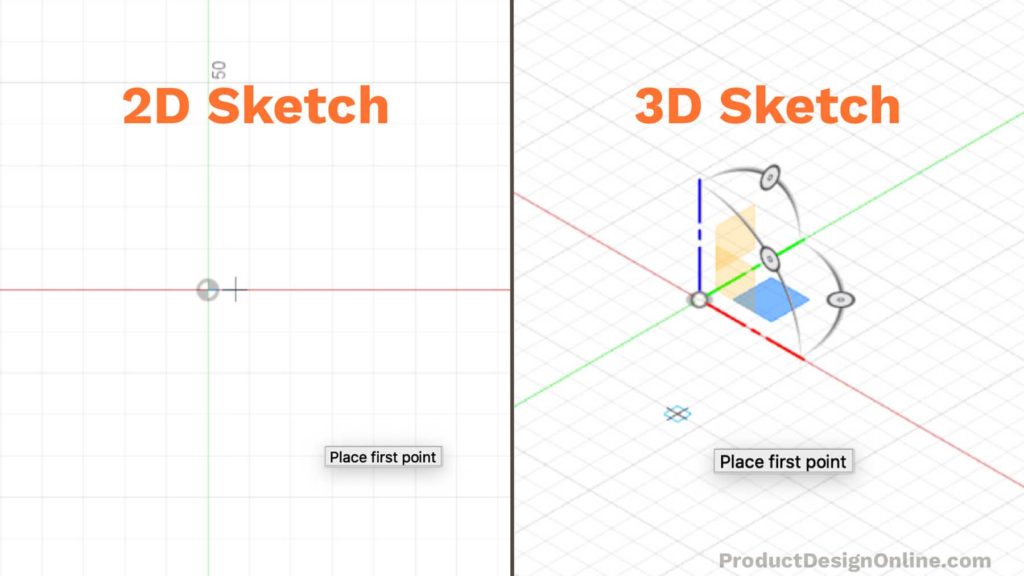
Differences Between 2D and 3D Sketching
In a 2D Sketch, we constrain sketch geometry to the airplane used to create the sketch. You can create a new second sketch on each of the post-obit:
- XY, YZ, or XZ origin planes
- Faces
- Construction planes
A 2d sketch plane can originate anywhere in 3D space. However, the selected aeroplane restricts sketch geometry to that plane.
With a 3D sketch, Fusion 360 removes the planar restriction allowing you lot to create sketch geometry anywhere in 3D infinite.
It'due south of import to note that 2nd sketches likewise exists as an individual Sketch characteristic in the parametric timeline. Yous'll frequently have several unlike sketch features that make up a design.
Opposite, 3D sketches will be one unmarried sketch feature in the timeline.
Sketch dimensions and constraints tin sometimes exist harder to update and manage with 3D sketches – making the concept ofblueprint intent harder.
Knowing when to utilise a 3D sketch instead of a 2D sketch tin can brand all the deviation.
When to Use 3D Sketches
There's no question that 3D sketches come with actress complexity. That may accept you wondering, "When should I use a 3D Sketch?"
In short, apply a 3D sketch to create a path for tubing, sweeps, lofts, or surface edges, when the design continues to multiple planes.
Use a 2D Sketch to create planar (flat) sketch geometry for mutual features similar extrude and revolve.
3D Sketches are as well practiced for:
- Routing
- Sweep Path
- Guide Curve
- Surface Extrudes
- Curve-Driven Patterns
- Carve up (Trunk) Lines
- Assembly skeletons
In summary, utilise a 3D sketch if it volition save time creating the model when compared to using traditional planes and second Sketches.
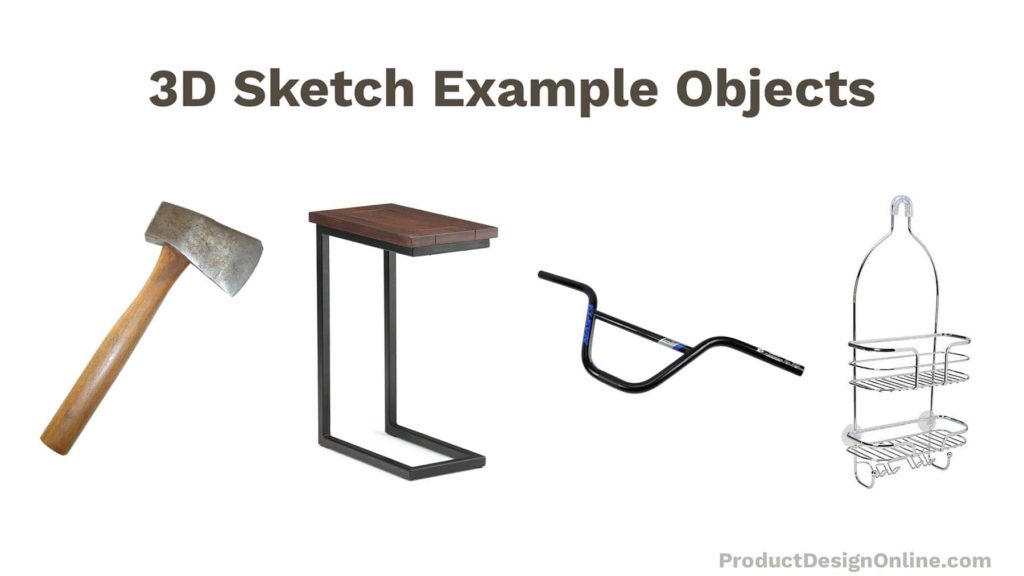
3D sketch instance objects:
- Bike handlebars
- Shower caddy
- Axe head
- Furniture with continuous shapes
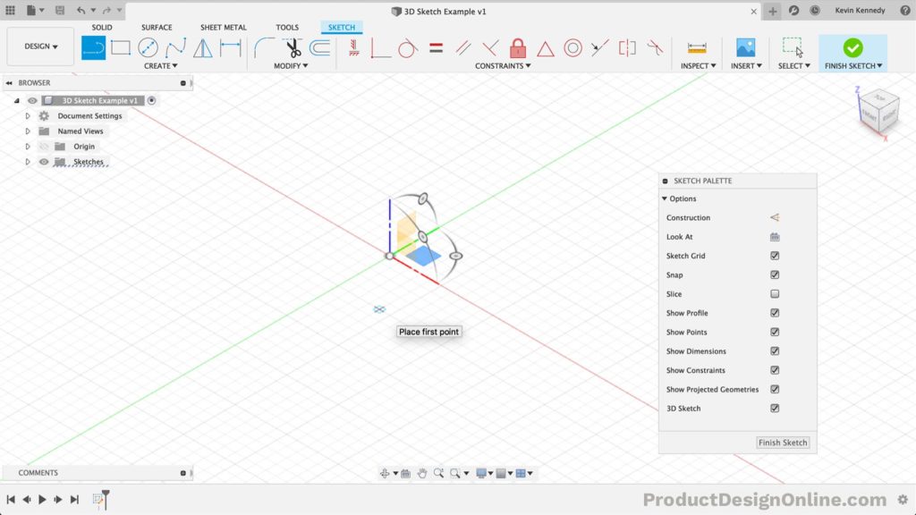
Create a 3D Sketch in Fusion 360
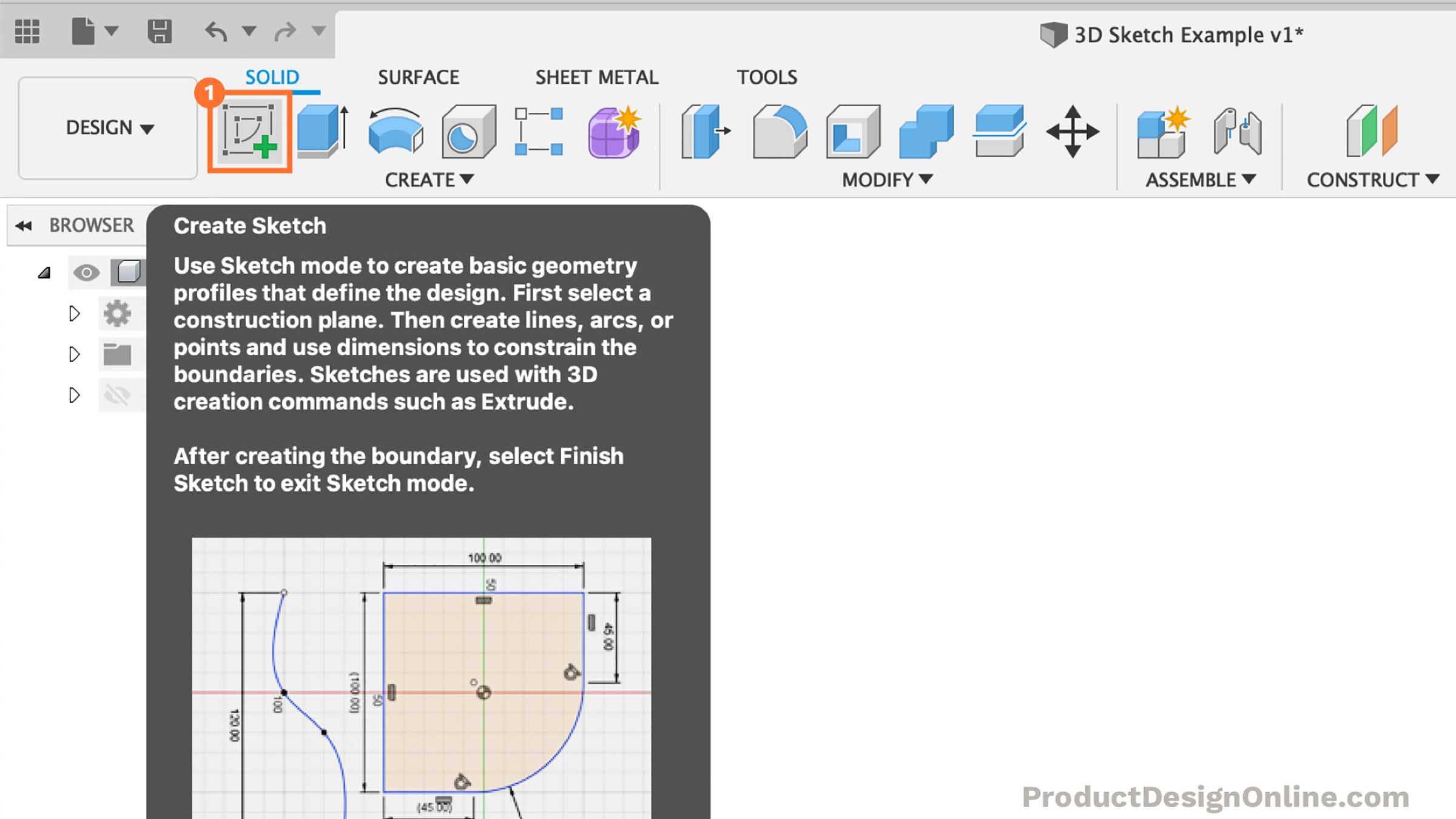
- Select theSolid tab in thePattern workspace. SelectCreate Sketch in the toolbar.
- Select the initial plane or face to begin the sketch on.
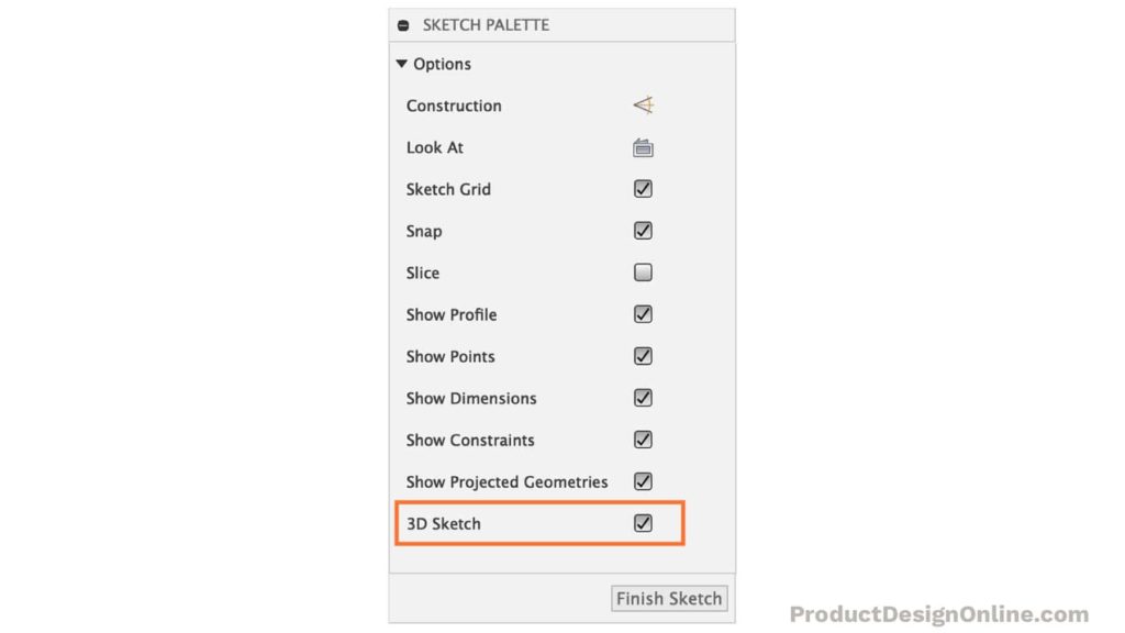
- Bank check the3D Sketch box in theSketch Palette.
- Select one of the sketch commands supported by3D Sketch. The 3D Sketch Manipulator will announced at the default location (0,0,0).
- Select a sketch plane or adjust the3D Sketch Manipulator. If desired, switch to a different sketch airplane by selecting it (XY, YZ, or XZ) or rotate the sketch airplane by dragging any rotation handle.
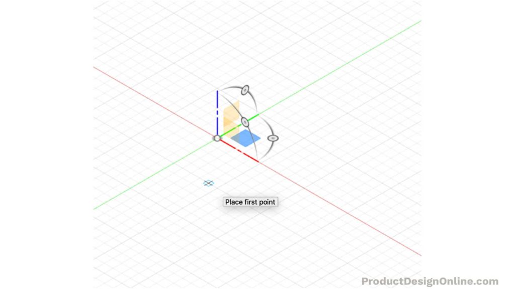
- Click anywhere on the active sketch aeroplane to create the first sketch point. Hover along the axis until its extension line displays, then click to place the indicate to restrict the point along an axis.
- Continue to place sketch points as desired. The origin of the3D Sketch Manipulator will shift to the final indicate y'all placed, equally you place 3D sketch points.
- ClickFinish Sketch in the toolbar to terminate the sketch.
Do 3D Sketch – Sweep a Side Table
Fourth dimension needed:20 minutes.
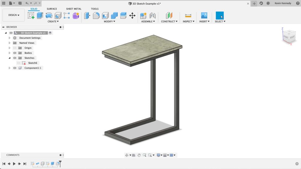
I happened to run across this "C Side Table" on Amazon and thought it was the perfect 3D Sketch beginner projection.
This table design could theoretically use 2nd Sketches. However, we can make the tablemuch faster using 3D sketches.
- SelectCreate Sketch in the toolbar
Kickoff the sketch past selecting the XY origin aeroplane. We'll click this plane to start by drawing the bottom of the table equally if it were sitting on the ground.
- Plough on 3D Sketch
Select the 3D Sketch checkbox in the Sketch Palette to plow it on.

- Activate Line & Home View
Select the line feature in the toolbar or hit the keyboard shortcut "L." Select the "Dwelling" position side by side to the ViewCube. This volition help us sketch in 3-dimensions.

- Depict First Line from Origin
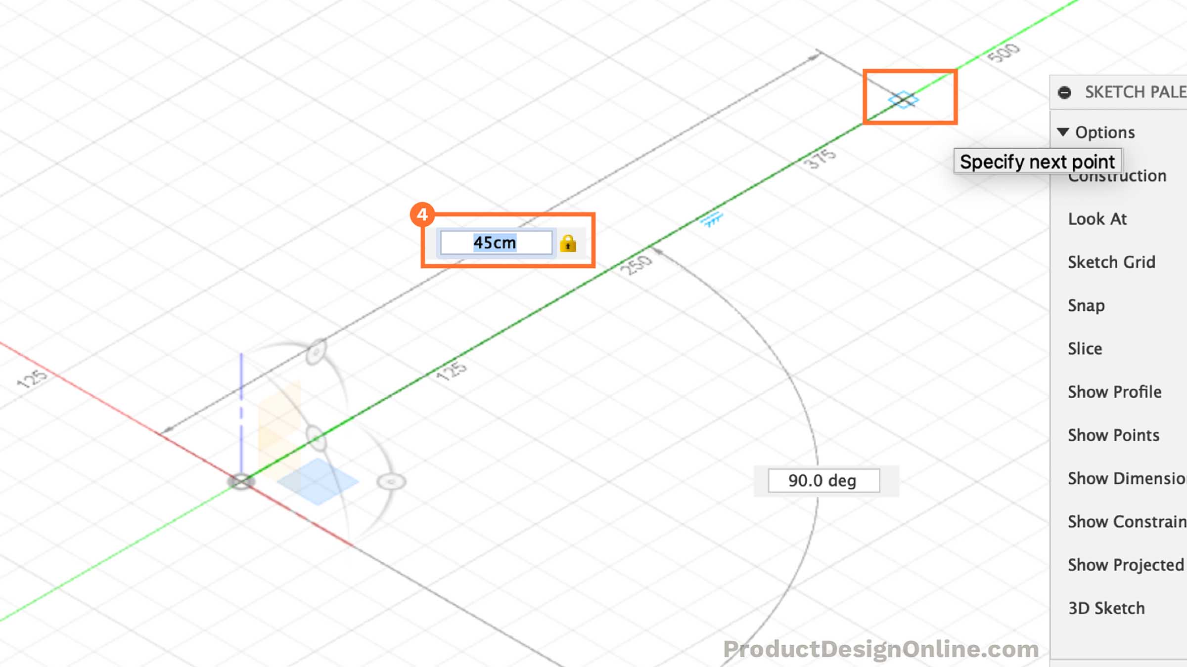
At this point, we can start the line by setting the first indicate at the origin bespeak.
Similar to a 2D sketch, nosotros volition drag our mouse cursor forth the green Y-centrality. Blazon out 45cm for the length and then click where the line snaps into the Y-axis. Fusion 360 will automatically add a "horizontal/vertical" constraint for us.
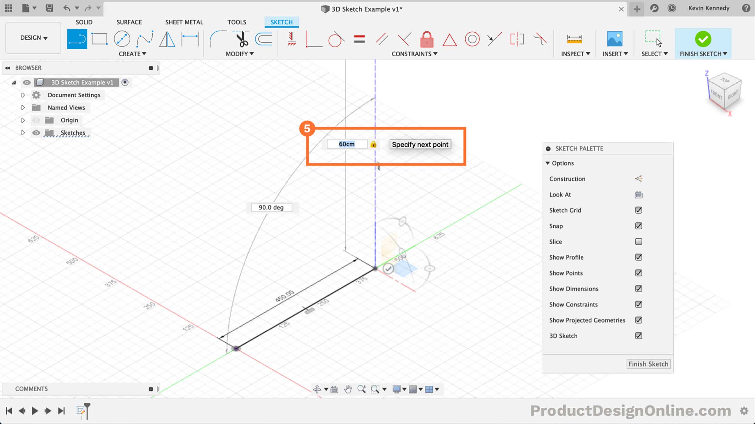
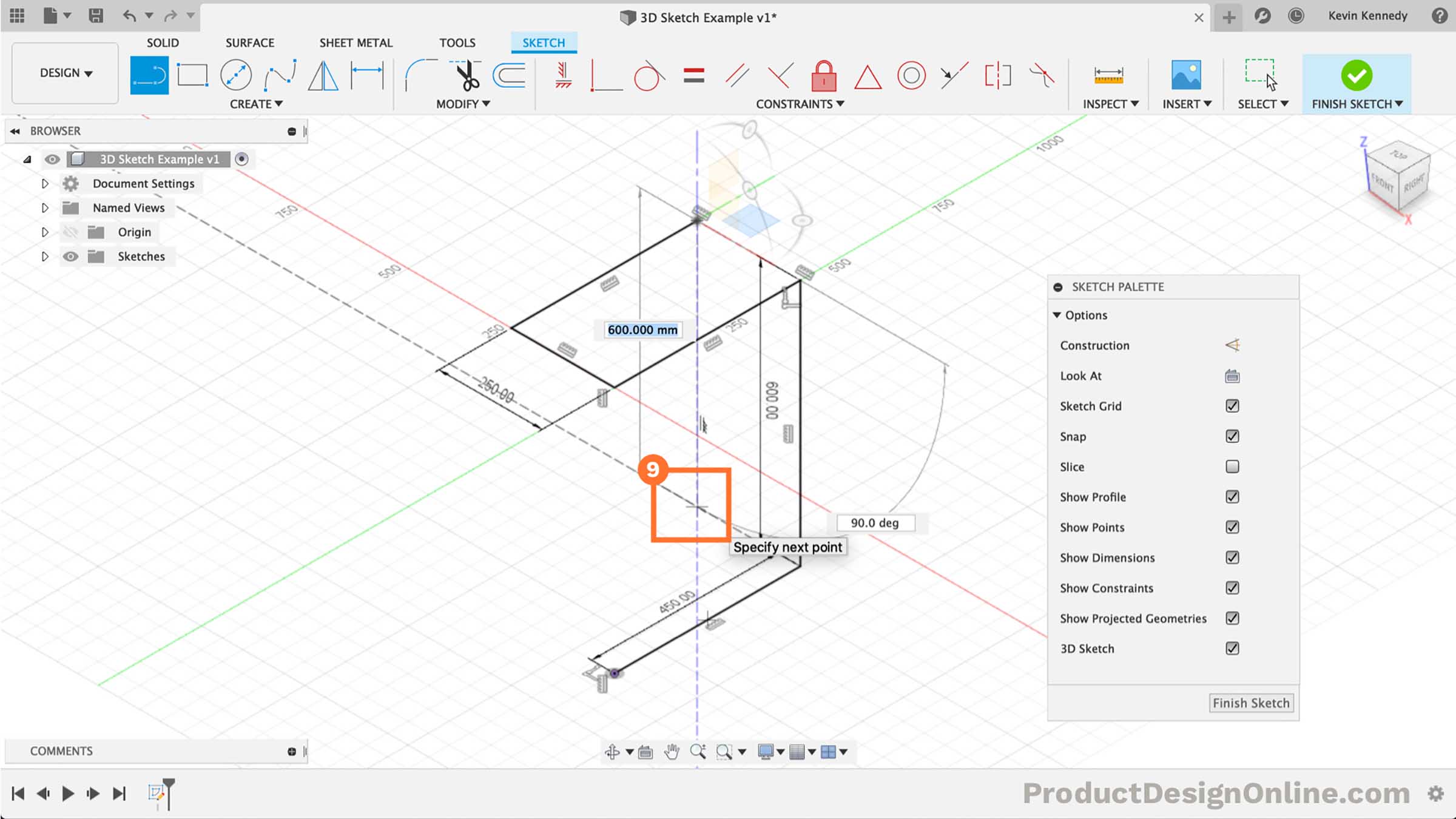
- Depict Line Direct Upward
We tin can start to sketch the height of the tabular array past moving our mouse cursor to the blue z-axis. The cursor should snap to the z-centrality when close.
Type out 60cm for the height. Carefully select the blueish z-axis to set the line, making certain it automatically add a vertical constraint.
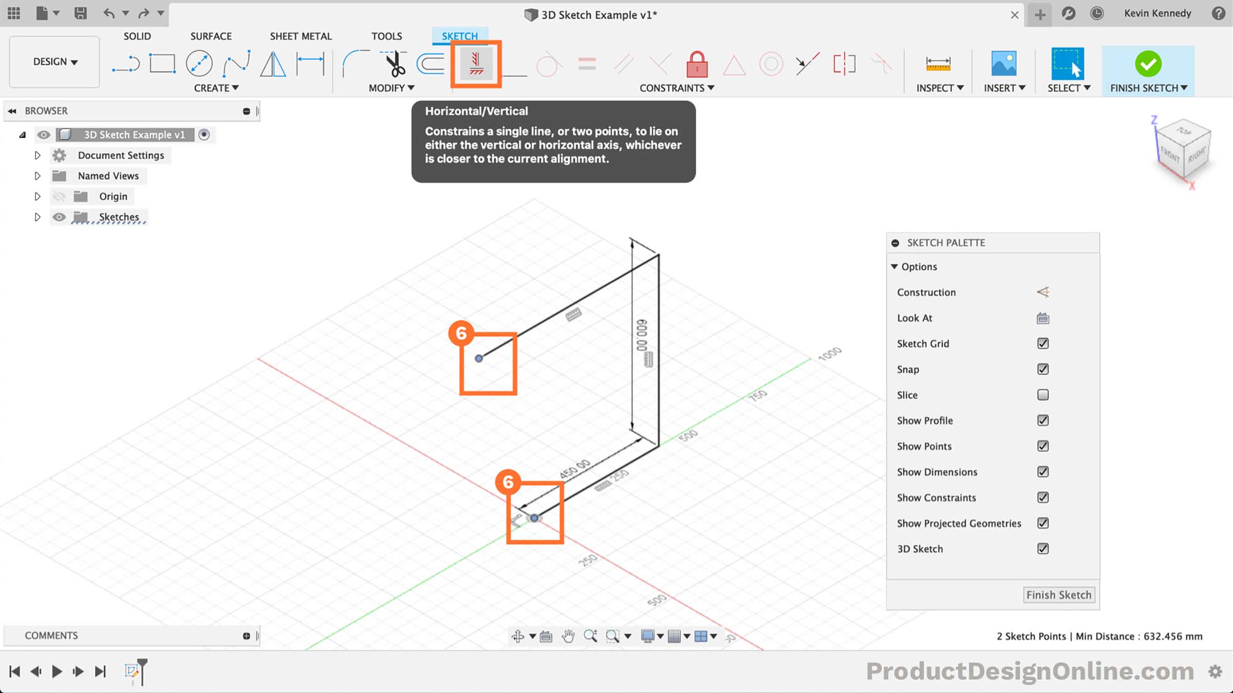
- Heading Back Toward Eye
For the third line, we'll desire to head back toward the eye, while following the dark-green y-axis. If yous haven't already noticed, run across that the origin planes motility to the cease of our line while in 3D sketch mode.
This is where things beginning to go tricky with 3D Sketches. We don't want to overuse sketch dimensions. Instead of typing out a dimension, click to identify the line forth the y-axis.
Shift-click the endpoints of the line we only placed and the origin point or the original starting point of our first line. Select the "horizontal/vertical" constraint in the toolbar. This will ensure they stay the aforementioned length while making it easy for us to update only one dimension.
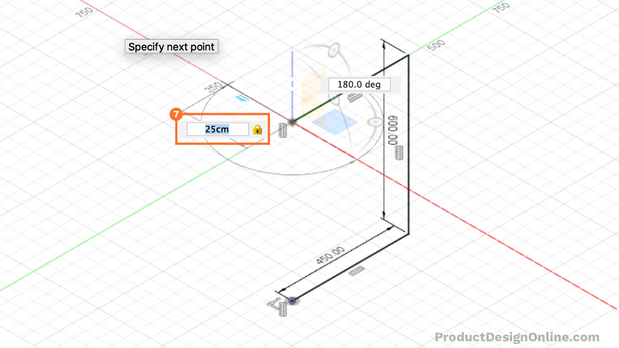
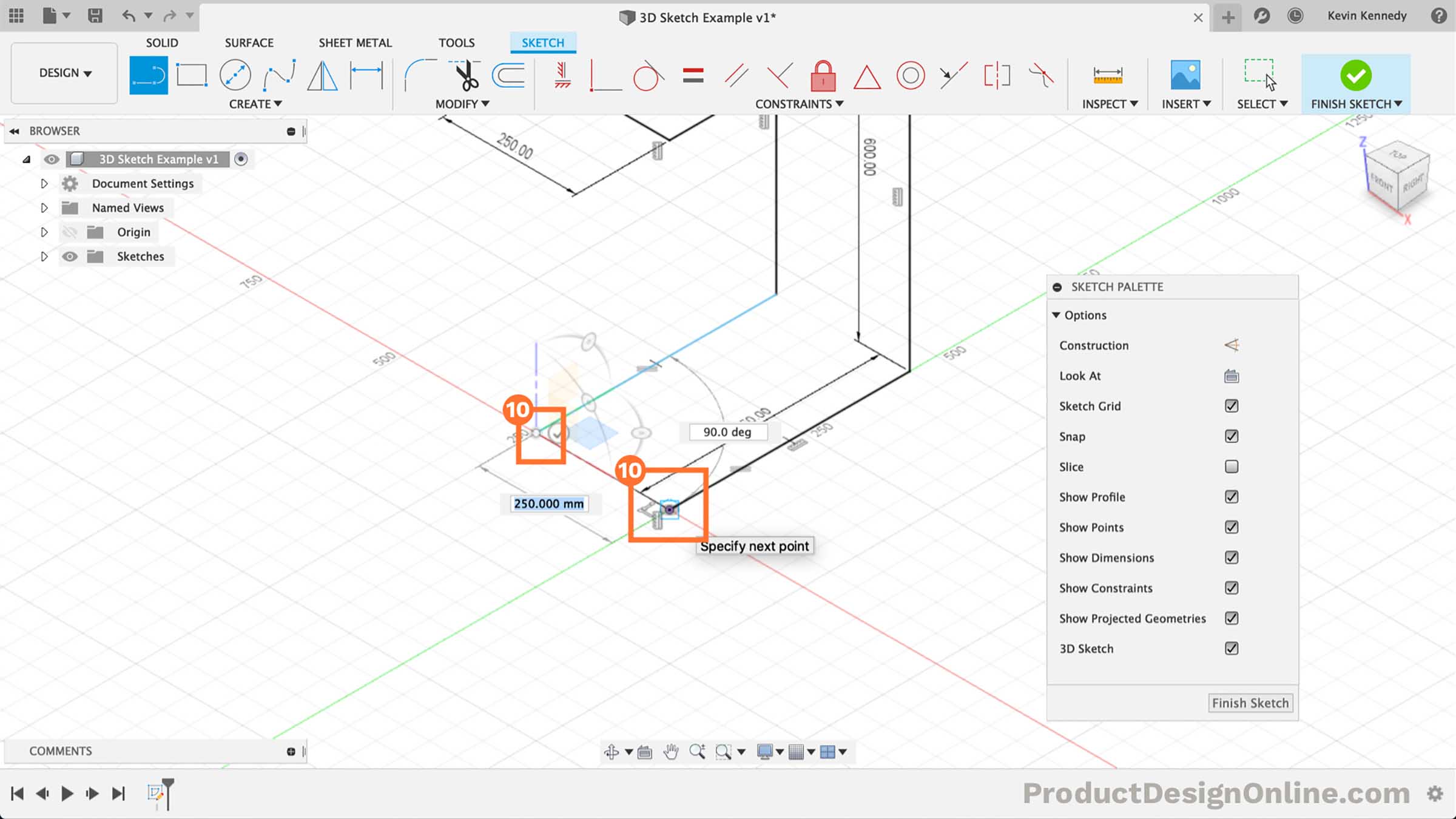
- Reactivate Line Command
Select the line feature in the toolbar. Select the endpoint of the line we just placed.
The 3D sketch planes and manipulators will reappear once you select the endpoint.
For this line, we'll type out25cm for the width. Make certain to snap the line in place along the cherry-red x-centrality.
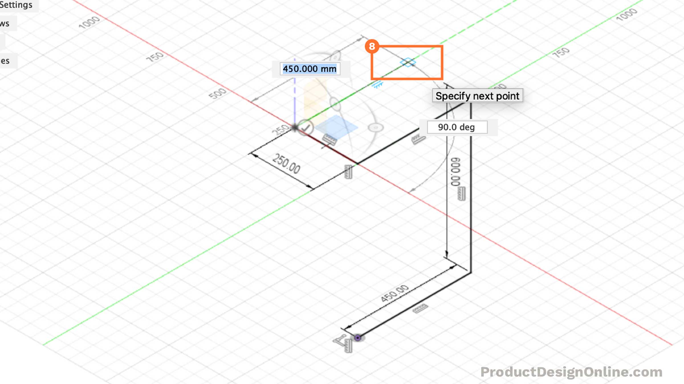
- Heading Dorsum to the Right
We'll now want to create a line heading back to the right.
Since we've already divers our length, we'll want to utilise sketch constraints instead of sketch dimensions for this i. Click along the light-green y-axis where the line snaps in at the aforementioned length of the contrary line.
Hit the "Escape" fundamental on your keyboard. Shift-click the endpoint of this line and the reverse line. Select the "Horizontal/Vertical" Constraint in the toolbar. This will force the line to stay the same length.
- Heading Straight Down
Reactivate the line command in the toolbar. Select the endpoint of the last line we created.
Heading straight down, click to identify the line along the blue z-centrality where it snaps equidistant to the opposite line. The line should exist 60cm.
- Finishing off The Lines
Allow'due south finish off the lines past mimicking the "C" shape on the opposite side.
Identify the first endpoint at the red y-axis. Create the second line by clicking the origin point.
Hit the "escape" central to articulate the line command.
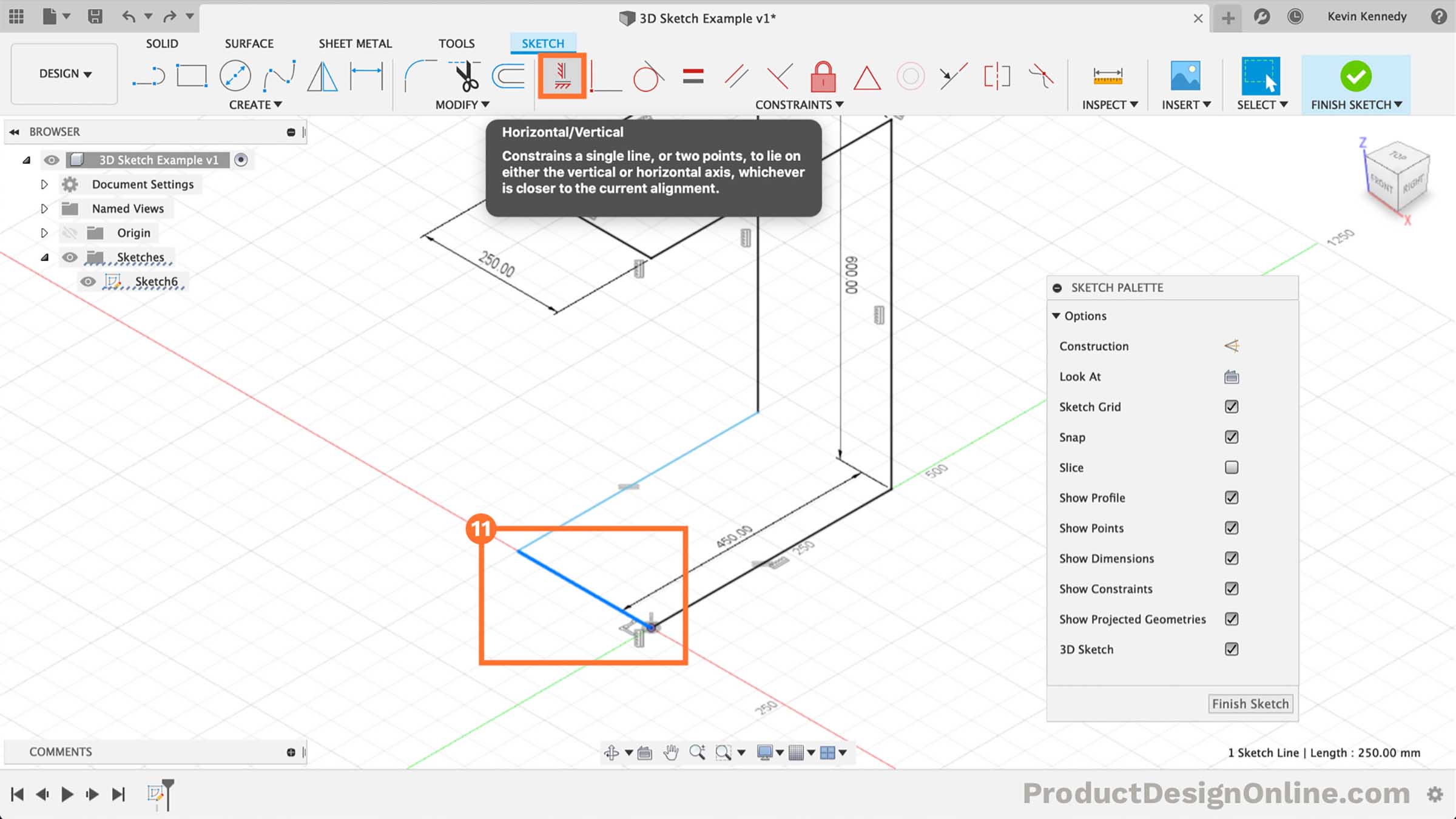
- Adding the Final Constraints
To ensure our sketch is fully-constrained, we'll need to add together the final constraints.
It appears the final line created does not have a constraint forcing it to remain in one direction. But select the line and then select the "Horizontal/Vertical" constraint in the toolbar.
Our sketch is now fully-constrained. We can double-cheque this past looking for the cherry lock icon next to the Sketch name in the Browser.
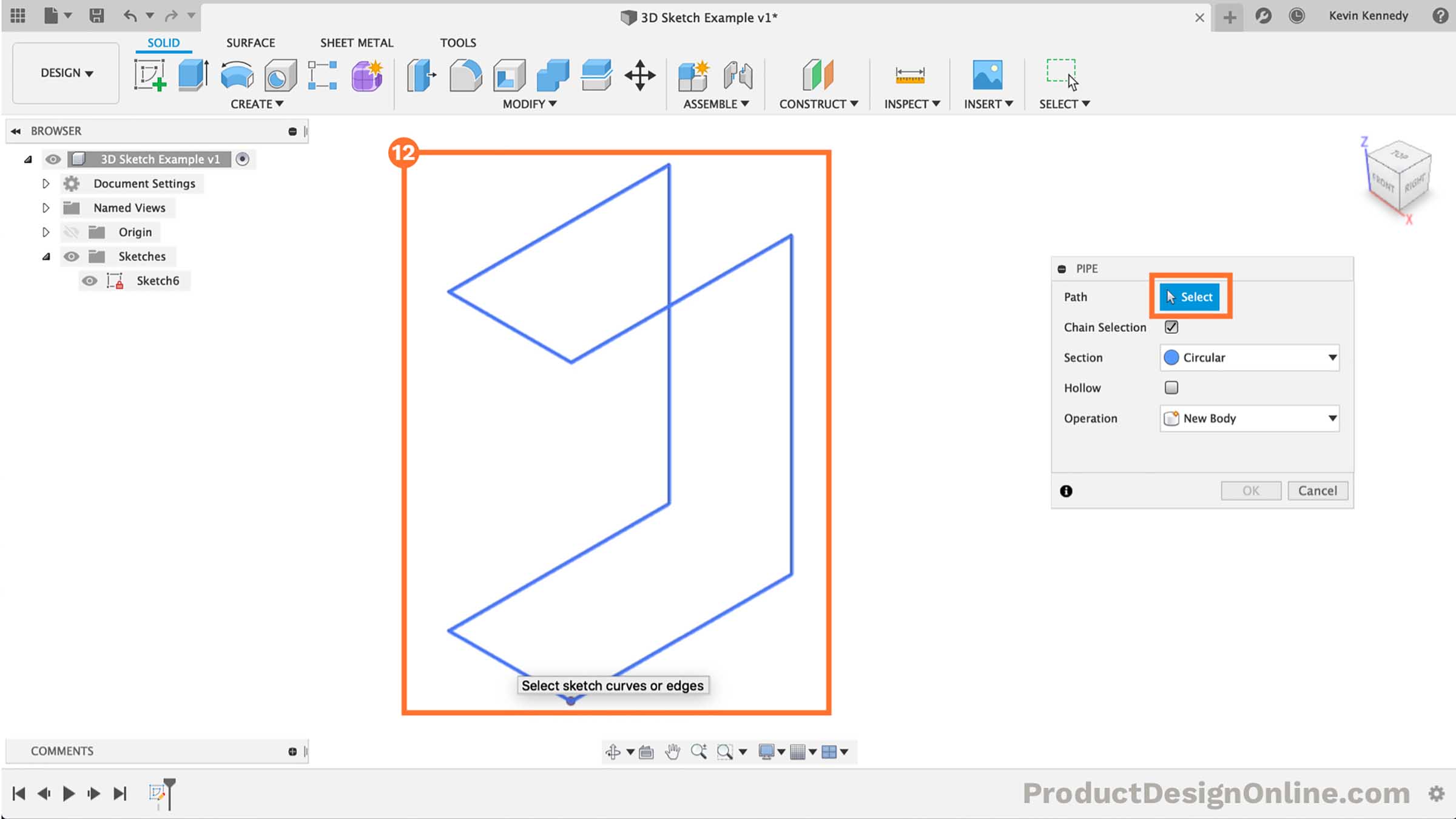
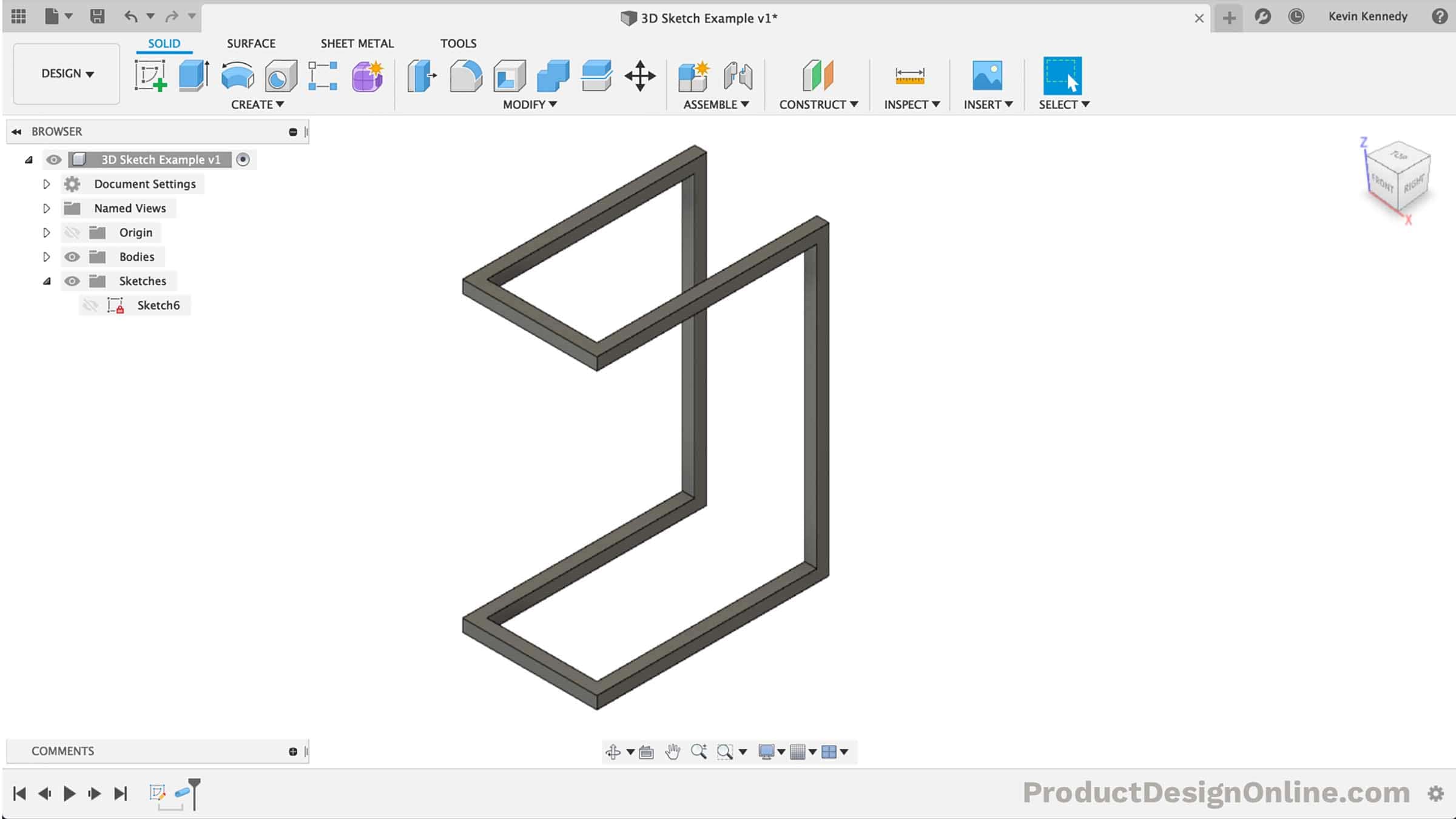
- Turning the Sketch into Pipes
Our sketch is now consummate. Nosotros're ready to use the Pipe command to plough the sketch into article of furniture.
Select theSolid tab in the toolbar. SelectPipage from theCreate dropdown. Select the 3D sketch geometry.
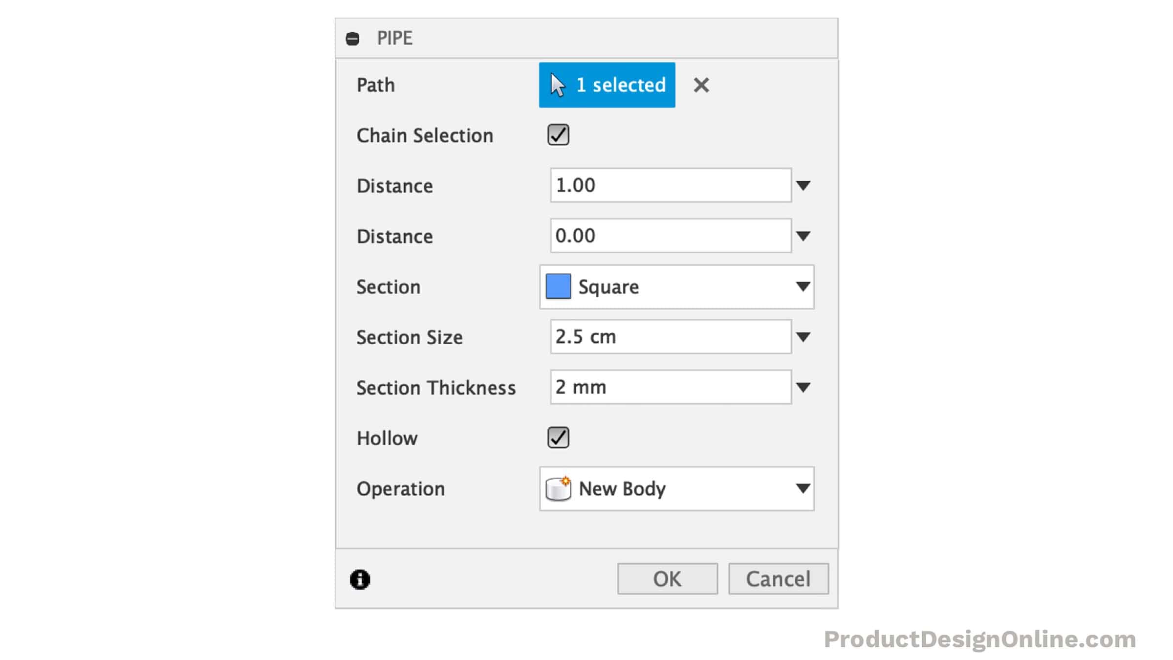
- Adjusting the Pipe Features
We'll want to prepare theSection blazon toFoursquare. We can also modify the thickness of the pipe by irresolute the department size.
I've enteredii.5cm for thesection size.
Select the "Hollow" checkbox, which displays thesection thickness. For the section thickness type out2mm.
- Congrats and Next Steps
Y'all've now completed the 3D Sketch! Cease off the model past adding boards to the elevation – or whatever surface you desire!
Source: https://productdesignonline.com/fusion-360-tutorials/introduction-to-3d-sketching-in-fusion-360/
0 Response to "how to draw 3d sketch in inventor"
Post a Comment